Ambient energy harvesting technology provides the most promising energy solution for future battery-less, ubiquitous, and maintenance-free Internet of Things (IoT) devices. Among all types of ambient energy sources, mechanical kinetic energy can be better associated with human and machine movements, as there is plenty of motion information combined with the mechanical movements of parts. The research on kinetic energy harvesting and its applications in future battery-less IoT devices has attracted many professionals’ attention, from scientists to engineers with different academic or engineering backgrounds, such as materials science, mechanical engineering, electrical engineering, and computer science.
The Mechatronics and Energy Transformation Laboratory (METAL), led by Prof. Liang Junrui at the Center for Intelligent Energy of Information Institute (CiPES) of SIST, recently developed a new piezoelectric kinetic energy harvesting circuit called Series Synchronized Triplex Bias-Flip (S-S3BF). This design improved piezoelectric energy harvesting capability through functional reuse of fewer peripheral capacitors. This new design used a single capacitor as an energy storage component as well as a positive and negative bias voltage source in a time-sharing manner. It is the first time that this method - synchronized triple bias-flip energy harvesting by maximizing the usage of a single storage capacitor - has been realized. The research work was published in the IEEE Transactions on Power Electronics, a leading academic journal on Power Electronics, in an article entitled “Series synchronized triple bias-flip circuit: maximizing the usage of a single storage capacitor for piezoelectric energy harvesting enhancement.”
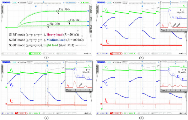
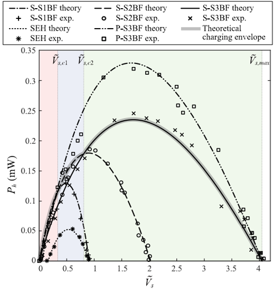
Prof. Liang Junrui and his METAL research group have worked on kinetic energy harvesting technology and battery-less IoT circuits and systems for many years. They also pioneered the synchronized multiple bias-flip (SMBF) circuit concept, which was developed based on a general understanding of the “maximum harvesting capability of the piezoelectric energy harvesting circuit.” In recent years, many leading integrated circuit (IC) designs incorporated this idea and endeavored to realize more voltage steps at the synchronized instants using switched-capacitor technology. However, with an expansion of the switch network and the increase in numbers of capacitors as bias voltage sources, the circuit control becomes more complicated, and the circuit topology also becomes more complex. This newly proposed design employed an alternate method to simplify complexity. It maintained the improvement in energy harvesting capability while also reducing the complexity of circuit topology. The system performance was optimized in a comprehensive, rather than a one-sided way. The S-S3BF circuit achieved a better piezoelectric energy harvesting capability compared with the other single-capacitor designs. Moreover, S-S3BF can automatically adapt to different loads by adjusting the number of bias-flip actions and maintaining a better working status under different loading conditions.
The research on S-S3BF was conducted at ShanghaiTech University. Zhao Bao, a master student graduated in 2020, was the first author of the paper. The corresponding author is Prof. Liang Junrui. The work was supported by the National Natural Science Foundation of China, the Start-up Funds of ShanghaiTech University, and an Open Fund from the Shanghai Key Laboratory of Mechanics in Energy Engineering.
Article link: https://ieeexplore.ieee.org/document/9264712

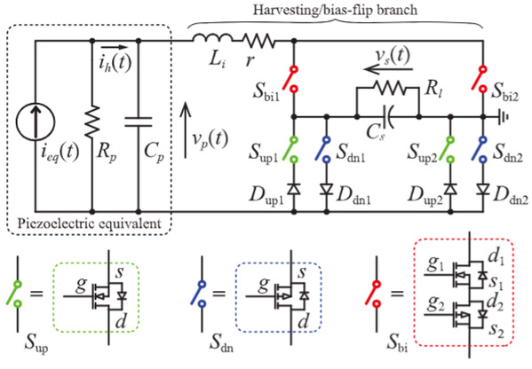
Figure 1. Schematic diagram of the series synchronized triple bias-flip (S-S3BF) energy harvesting circuit

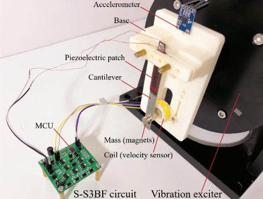
Figure 2. Experimental setup and testing platform

Figure 3. Operating waveform of the S-S3BF circuit. (a) Charging waveform. (b) Single voltage bias-flip under a heavy load. (c) Double voltage bias-flip under a medium load. (d) Triple voltage bias-flip under a light load

Figure 4. Comparison of the power of the kinetic energy harvesting circuit